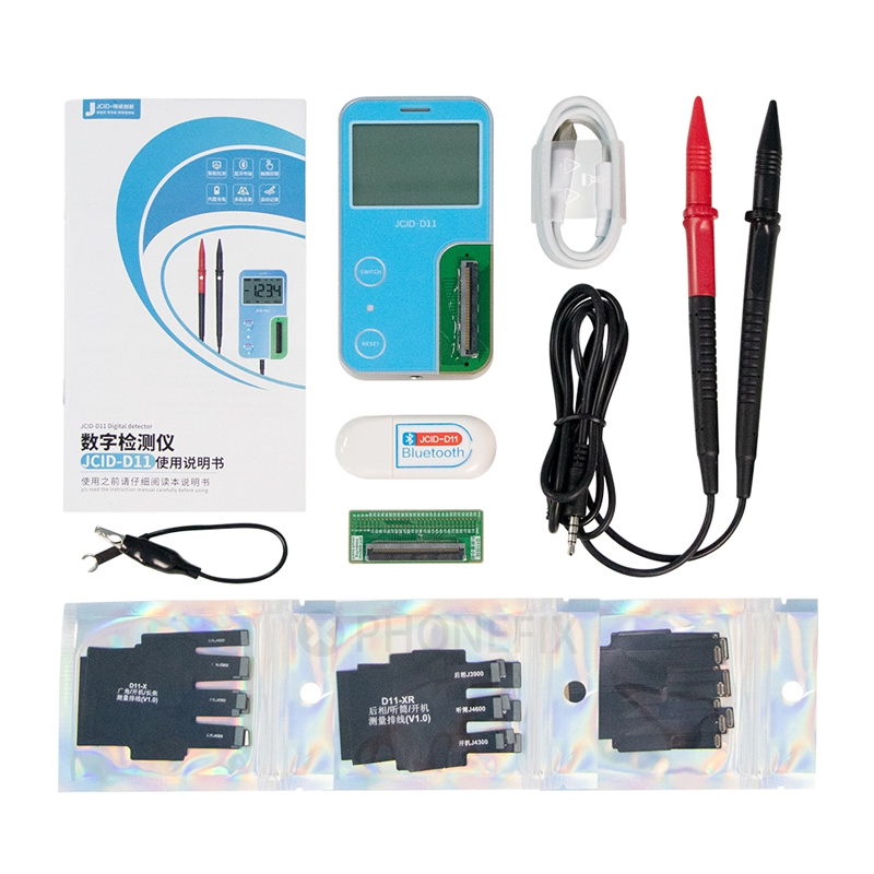
JCID-D11 digital detector has been released and is wildly popular. JCID-D11 digital detector supports measuring the voltage, resistance, diode, and short-circuit data of the iPhone motherboard. How to use JDID-D11? JCID D11 supports use with JCID Drawing diagrams and external multimeter probes and measuring flex cable. Therefore, the JCID D11 digital detector has several operation methods.
1. JCID-D11 works with the measuring flex cable.
Tools needed: JCID Drawing diagram software, JCID-D11 digital detector, external measuring flex cable, JCID-D11 bluetooth adapter, iPhone motherboard.
- Open and log in to the JCID Drawing software, find and open the drawing of the model you want to measure in the catalog, click “Digital Detection” in the lower right corner of the software interface.
- Plug the Bluetooth adapter into the USB port of the computer, boot the JCID-D11, and connect the motherboard and the JCID D11 with an external measurement flex cable.
- Go back to the “Digital Detection” interface and click “Install Driver” above to install the driver.
- Click the “Refresh” button, search for JCID-D11 Bluetooth, and then tap the “Connect” button. After the connection is successful, select the components in the diagram bitmap to start measuring the voltage/resistance.

2. Online operation with multimeter lead probes.
Method 1: For DC voltage, resistance, short circuit, diode value measurement.
Tools needed: JCID Drawing diagram software, JCID-D11 digital detector, multimeter lead probes, JCID-D11 bluetooth adapter, iPhone motherboard.
- Open and log in to the JCID Drawing software, find and open the drawing of the model you want to measure in the catalog, click “Digital Detection” in the lower right corner of the software interface.
- Plug the Bluetooth adapter into the USB port of the computer, boot the JCID-D11, and connect the lead probes.
- Go back to the “Digital Detection” interface and click “Install Driver” above to install the driver.
- Click the “Refresh” button, search for JCID-D11 Bluetooth, and then tap the “Connect” button. After the connection is successful, click on the view selection, and then select the components to be measured in the diagram bitmap.
- Connect the test probes to the test point reliably, press and hold the touch button on the test probes, the data will be automatically recorded in the JCID Drawing software.

Method 2: For DC voltage, resistance, short circuit, diode value measurement.
Tools needed: JCID Drawing diagram software, JCID-D11 digital detector, external measuring flex cable, multimeter lead probes, JCID-D11 bluetooth adapter, iPhone motherboard.
- Open and log in to the JCID Drawing software, find and open the drawing of the model you want to measure in the catalog, click “Digital Detection” in the lower right corner of the software interface.
- Plug the Bluetooth adapter into the USB port of the computer, boot the JCID-D11, and connect the lead probes.
- Go back to the “Digital Detection” interface and click “Install Driver” above to install the driver.
- Click the “Refresh” button, search for JCID-D11 Bluetooth, and then tap the “Connect” button. After the connection is successful, click on the view selection, and then select the components to be measured in the diagram bitmap.
- Connect the iPhone motherboard with an external measuring flex cable.
- Connect the test probes to the test point reliably, press and hold the touch button on the test probes, the data will be automatically recorded in the JCID Drawing software.

3. Offline operation with multimeter lead probes.
Tools needed: JCID-D11 digital detector, multimeter lead probes, iPhone motherboard. For DC voltage, resistance, short circuit, diode value measurement.
Voltage measurement:
- Turn on the JCID-D11 digital detector, and connect test lead probes to the JCID-D11.
- Switch the JCID-D11 function to the voltage interface.
- Reliably touch the measuring probe to the test point, and the screen will display the voltage value.
Resistance measurement:
- Turn on the JCID-D11 digital detector, and connect test lead probes to the JCID-D11.
- Switch the JCID-D11 function to the resistance interface.
- Tap the test probes to the measured resistor, and the screen will display the resistance value.
Diode and continuity test.
- Turn on the JCID-D11 digital detector, and connect test lead probes to the JCID-D11.
- Switch the JCID-D11 function to the diode interface.
- Connect the test probes to the measured diode, and the value displayed is the nearsighted value of the forward voltage drop of the diode. For a silicon PN junction, generally about 500mV-800mV is confirmed as a normal value. If the tested diode is open circuit or acute reverse connection, it will display”0L”.
- Trigger the “Switch” button, select the buzzer measurement, and connect the test probes to the two points of the line to be tested. If the built-in buzzer sounds, the resistance between the two points is low 50Ω.


